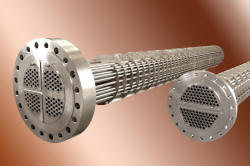
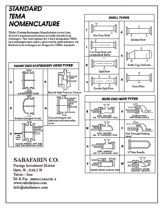
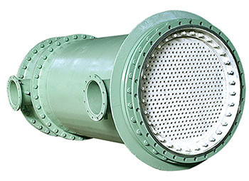
Shell and Tube Heat Exchanger Types:
- U-Tube bundle heat exchangers consistent with standard types TEMA BEU/AEU;
- Heat exchangers with fixed tube sheet consistent with standard types TEMA BEM/AEL;
- Heat exchangers with floating tube sheet consistent with standard types TEMA AEW, AES, AET, AEP;
- All class TEMA B, C, R heat exchangers.
Production Capabilities:
The production capabilities of Sabafarin company in manufacturing shell and tube heat exchangers are as follows:
- Shell diameter up to 2.5m;
- Maximum tube sheet thickness up to 200mm;
- Complete facilities for tube sheet manufacturing including drilling, grooving, reaming, etc. according to ASME and TEMA standards;
- Complete facilities for rolling and welding of tubes to tube sheets according to ASME and TEMA standards;
- Applying modern technology for tube bending with NC and C.N.C apparatus;
- Complete welding facilities including TIG, MIG/MAG, SMAW and SAW;
- Complete facilities for sand blasting and coloring the manufactured heat exchangers;
- Complete facilities for hydro testing up to 500 bars;
- Up-to-date technologies for manufacturing of various fin tubes.
- Complete tools for repairing, rebuilding and assmbling of the heat exchangers.
Thermal design:
Thermal design is performed based on the required technical data provided by customers, using HTRI, APEN, HTFS, etc. sofware. The best model from viewpoints of cost and technical is then opted, taking advantage of our several years of experience in this field. The following write-up provides general design information for those engineers not familiar with the design of shell & tube heat exchangers:
Heat Load Balance:
The first step in ensuring that a heat exchanger is properly designed is to calculate the thermal duty . The thermal duty is the amount of heat transfered per unit time (Btu/hr).
For fluids not undergoing a phase change ( sensible heating/cooling ), the thermal duty is equal to:
Q= Cp ( T1-T2) m
Q = Thermal Duty ( Btu/hr)
Cp=Heat Capacity (Btu/Ib F)
Tl=Inlet Temperature (F)
T2=Outlet Temperature (F)
m=Mass Flow Rate (Ib/hr)
For fluids undergoing a phase change, the thermal duty is equal to:
Q= m Lamda
Q=Thermal Duty (Btu/hr)
m=Mass Flow Rate (Ib/hr)
Lamda= Latent Heat (Btu/hr)
In cases where the fluid undergoes both sensible heating and a phase change, simply add the sensible duty (for both the liquid phase and in the vapor phase as required) to the phase change duty.
The thermal duty on the hot side must equal the thermal duty on the cold side therefore, after calculating the duty for the process side, use this duty to calculate the flow rate or outlet temperature for the heating or cooling medium .
Sizing Formula:
After the thermal balance is confirmed, the next step in the process is to properly size the heat exchanger . The governing equation for determining the size of the exchanger is as follows:
Q= U A MTD
Q=Thermal Duty (Btu/hr)
U=Overall Heat Transfer Coefficient (Btu/hr ft2 F)
A=Area (ft2)
MTD=Mean Temperature Difference (F)
The thermal duty calculated from this formula must equal (or exceed) the thermal duty required from the heat balance.
Overall Heat Transfer Coefficient:
(\"U\" value ):
The U value is a function of the physical properties of both the hot fluid and cold fluid, the fouling factors applied, and the fluid flow dynamics through the heat exchanger. When designing a heat exchanger, the engineer tries to maximize the U value in order to minimize the required surface area.
U Value Versus Pressure Drop:
When specifying the allowable pressure drop through the heat exchanger, customers should give the heat exchanger manufacturer as much allowable pressure drop as possible. Higher allowable pressure drops allow higher velocities through the heat exchanger, increasing the heat transfer coefficient.
Area:
The area available is equal to the outside surface area of the tubing. When finned tubes are used, this heat transfer area is substantially increased however, often the U value will drop as the finned surface area is not as effective is providing heat transfer as the surface of a bare tube.
MTD:
The MTD is a measure of the temperature difference between the hot fluid and the cold fluid. The greater the difference in temperature between the hot fluid and the cold fluid, the lower the required surface area.
Mechanical Design:
The MTD is a measure of the temperature difference between the hot fluid and the cold fluid. The greater the difference in temperature between the hot fluid and the cold fluid, the lower the required surface area.
Heat exchangers are mechanically designed according to the following standards:
- ASME SEC VIII DIV 1,2;
- TEMA;
- API 660.
In addition, the heat exchanger drawings are prepared by the latest version of AutoCAD and CATIA and are sent to our customers by fax or email.
Quality Control:
Heat exchanger quality control is executed according to TEMA and ASME standards and heat exchangers are delivered to the customers with a completed quality pass. Also we might request a technical inspection company to perform quality control once required.
Heat Exchanger Production Material:
The appropriate materials used for manufacturing of heat exchangers are chosen based on the fluid or vapor flowing in the heat exchanger, working conditions such as pressure, temperature, etc., finished costs, durability, repairing and maintenance services.
Heat Recharger Tubes:
- Heat exchanger tubes could be whether welded or seamless, and selected from different types of materials.
- Tube sizing is usually chosen based on the tube\'s outer diameter and thickness. The heat exchangers tubes are usually between Ø 3/8" and Ø 2". The most common sizes are Ø 5/8" and Ø 3/4", which are also more cost effective.
The utilized tube materials in Sabafarin company include:
- Welded and seamless carbon steel tubes;
- Stainless steel tubes of groups 300 and 400;
- Copper tubes;
- Copper-Nickel tubes;
- Aluminum-Brass, Admiral-Brass and Brass tubes.
Shell:
Shells are typically made from carbon steel, stainless steel, and rarely brass and copper.
Tube Sheet:
Tube sheets are typically made from carbon steel, forged carbon steel, stainless steel, and rarely brass and copper.
Tube Bundle Replacement:
Sabafarin company is able to manufacture and replace any type of existing tube bundle matching the accessible measures and compatible with the required performance and materials. Our company is proficient in manufacturing of U-Tube bundles, tube bundles with floating tube sheets, and tube bundles with fixed tube sheets. We are not limiting our heat exchangers to a specific material. While most of the tube bundles are manufactured with copper tubes and carbon steel tube sheets, our heat exchangers could be also made of other materials such as copper-nickel, carbon steel, brass, admiral brass, stainless steel, etc.
Industries Served:
Our company's shell and tube heat exchangers are used in the following industries:
- Heating and cooling industries;
- Petroleum, gas and petrochemical industries;
- Food and hygienic industries;
- Wood and paper industries;
- Power plants;
- Metallurgy, minerals, and casting industries.
Heat Exchanger Design and Selection:
Shell and tube heat exchanger are among the most simple design, which do not include moving parts. These heat exchangers work based on the heat transfer between the fluid moving in the tubes (whether liquid or vapor) and another fluid flowing in the outside of tubes (in the shell).
Four basic points should be taken into account in determining the mechanical gement and for obtaining an acceptable heat transfer between two fluids:
- Paying attention to differential thermal expansion between shell and tube;
- The arrangement of the fluid passing through the tubes;
- Fluid flow on the shell side;
- Considering the servicing method and disassembling the heat exchanger.
Differential Thermal Expansion:
Since the temperature of the fluid inside the tubes differs from the fluid in the shell, tubes expand differently, for which several considerations in design should be applied:
- U-tube design:
The tubes in these heat exchangers are bonded like hairpins and the two ends of the tubes are connected to the tube sheet with expansion method. In these types of heat exchangers, the tubes are simply expanded without any connection to the shell, which causes no problem in expansion of the tubes and the shell.
- Floating head design:
In this heat exchanger, one of the tube sheets is fixed and the other is floating, in which there is no issue with the expansion of tubes and shells.
- Fixed tube sheet design:
n these heat exchangers, the tubes are connected to tube sheets, which are also welded to the shell. By placing a expansion joint in the middle of the shell and welding it to the shell offset the effect of thermal expansion.


Pass Arrangement for Flow through tubes:
The simplest flow pattern is a flow that the fluid enters to the tubes from one side of the tubes and leave from the other side. These tube bundles are called single-pass and are used in some processes; however they are rarely utilized. In order to accelerate the heat transfer, the flow rate in tubes should be increased, which becomes more practical by increasing the number of passes (by placing partition sheets) in the inlet of tubes. In bundles with fixed tube sheet, several partition sheets could be placed in the inlet and outlet sides of the tube sheets.

Shell Side Fluid Flow:

- Tube Supports:
The high length of tubes and their relatively low diameter in shell and tube heat exchangers might result in bending of the tubes and cause vibrations in long bundles. To prevent this, tube supporting sheets are installed on the tube bundle with specific distances from each other. Although the tube supports might influence the flow on the shell side, they are basically responsible to hold the tubes in the tube bundle.
- Baffles:
The baffles modify the flow conditions on the shell side and increase the heat transfer coefficient on the shell side. Without baffles, the flow enters from one end of the shell, spreads in the tube bundle and leaves from the other side at a low velocity and in form of parallel flow.
Maintenance and Servicing Considerations:
Maintenance and servicing should be considered in design of heat exchangers. Especially when a fouling fluid passes through the tubes, the user should be able to simply brush and cleanse the tube interiors.
Installation and Operation Considerations:
In order to take advantage of the heat exchangers in the best way, the following points should be considered:
- The fluid with higher temperature should pass from the shell side (outside of the tubes) while the cooling water passes through the tubes
- If an automatic water regulator valve is being used, it is better to be located on the inlet of the water to the heat exchanger. In addition, the outlet water piping should be designed in a way that the heat exchangers remains full of water at all times. A temperature probe must be also installed on the header sides of the heat exchanger.
- In order to discharge the flow on both shell and tube sides, drainage should be installed on the heat exchanger. Also a vent should be considered to discharge the trapped air.
- In case that tap water is being used, a grid (filter) should be placed in the heat exchanger\'s inlet in order to prevent fouling.
- Heat exchangers with fixed tube bundles are not recommended to work with steam. Heat exchangers with floating tube bundles should be used instead.
- The heat exchanger tubing system should be supported appropriately in order to prevent from excessive pressure on inlet and outlet nozzles. Additionally, in case that excessive vibration is observed, it is recommended to place shock absorbing mounts and flexible connections.
- The gaskets should be changed whenever the heat exchanger shell is opened up. In order to seal the system and prevent from corrosion, the gaskets should be lubricated.
- Salt water can not be used in standard models. Instead, a heat exchanger with, for example, copper-nickel tubes and tube sheets (dia. 90/10) might be used.
- Whenever the zinc anodes are utilized for specific needs, they should be inspected 2 weeks after the heat exchanger s first start. Meanwhile, by quick inspections of the anode and determining the corrosion rate, the frequency of the future inspections and controls could be verified .The anodes must be replaced after 70% of their volume was corroded.
- In temperatures below zero, water-freezing phenomena could be avoided by discharging the heat exchanger water.
- It is sometimes required to clean the cooling tubes and remove any fouls and sludge. This could be done with a 50% solution of muriatic acid in water (containing metal and steel anti-corrosion compounds). In order to improve the results, brushes that do not scratch the tubes could be used for cleaning purposes . At the end, the working environment could be neutralized and the heat exchanger could be safely returned back to work.